


Description
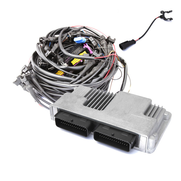
Vialle LSi : 6CYL ECU (F6)
Description:
The F‐module contains the ECU, the fuel switch, the full wiring loom, the temperature sensor and the fuses. The ECU called the TEC‐unit, calculates the injection times of the LPG Injectors. It uses different signals to detect the RPM and, engine temperature. Using module the software program can be started on your computer. The software is used to set‐up and calibrate your TEC‐unit and to diagnose problems. The fuel switch is positioned inside the car and must be in easy reach of the driver. It switches the chosen fuel and displays the amount of LPG left in the tank. The wiring loom consists of the main connector and several smaller wiring looms running from the main connector to the specific components. 2 longer wiring looms run to the tank at the back and the fuel switch in the interior.
Installation:
TEC‐unit (ECU) The TEC‐unit, like all other electronic equipment, should be placed in a relatively cool and dry location in the engine bay. A good position is usually near to the car battery. The optimal orientation for the ECU is with the connector facing downwards.
Fuel Switch:
The fuel selection switch is placed in the interior of the vehicle within easy reach of the driver. Mount the fuel selection switch back cover using the supplied adhesive sticker, do not apply force onto the centre of the switch but only onto the sides and edges. You may also use the supplied screws to install the back cover.
Wiring loom
The wiring looms connector forms the base for the smaller wiring looms running to the different components in the vehicle:
- Petrol Injectors -> the petrol connectors are interrupted using the Male‐ and female connectors on the wiring loom
- Car battery -> the red wire with the 15A fuse
- Engine ground -> the double black wire
- Ignition signal -> Ignition coil +
- RPM signal -> Ignition coil – (optional: if not possible, refer to the Quick Guide Software)
And to the LiquidSi modules
- The long (± 7m) wiring loom is used to connect the Fuel Module to the TEC
- The male 2‐pole connector with the blue wire and the ground
- The male 2‐pole connector (Yellow/Black) is used for the Temperature sensor.
- The male 4‐pole connector is only used when module is connected, always refit the plastic cap after using.
Installation notes:
The wiring loom should be kept at a safe distance from heat sources, sharp edges/objects and scraping against moving parts.

0 Reviews
Related Products


VIALLE
6CYL: Vialle LSi - Liquid Injection Kit

")
VIALLE
Vialle LSi : 4CYL ECU (F4)


VIALLE
Vialle LSi : 8CYL ECU (F8)

VIALLE
Vialle LSi: Solenoid Accessories Set (C2)


VIALLE